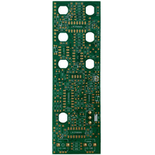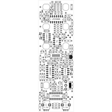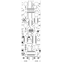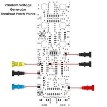
The RANDOM VOLTAGE GENERATOR produces random voltages which vary smoothly or in a stepped manner. Random timing pulses are also available. Rate of change of all outputs is voltage controllable over a wide temporal range. PLEASE NOTE: The noise source and S/H source are built into the module and does not require the NOISE SOURCE module to function. White, Pink and the S/H source are available via the corresponding pads located on the back of the module. These pad can be broken out to external jacks to offer a full range noise source. Note - If you choose to add these options then the module will become a 3 column unit as shown in the Panel EXT file.
J201 SMT Replacement (included in BOM)
Random Voltage Generator Panel's
LED Assembly x 3
This module requires 2 CA3080's that can be purchased HERE
LED Drivers (optional) - 2 x Bi-polar LED Driver, 1 x Uni-polar LED Driver
*CAPACITOR X AND WHITE RESISTOR ARE NOT USED*
CALIBRATION
NOTE - The PN4250 in white is the Noise transistor and will require some measuring before soldering the component into place. It is best to just place the part into this footprint while doing your final measuring. Order about 10 extra components to ensure the quality of the overall functionality.
Monitor the WHITE NOISE pad output and patch it into your Oscilloscope. Set the scope to read RMS measurements so you can determine the noise's range that should be in the range of 1.3v and 1.68v. Anything over that and the noise waveform may start to clip, limiting the range of the random outputs internally.
Now probe all other pad outputs to determine the functionality of the module is working correctly.
Once everything is working correctly, patch the stepped output into an oscillators frequency input. Now adjust the stepped trim pot so that the stepped output is at its max random voltage.
On to the timing adjust trim pot. This will set the overall frequency of the modules functionality. Adjust to taste.
Power Consumption
+12V - 70mA
-12V - 58mA
*Inspired by Serge Modular Music Systems*


